Cooling System Design for a Formula SAE Car, from Zero to One
From working out the heat, choosing the loop, to finding the radiators and the pump: how I designed the cooling system for our Formula SAE electric car, and which parts still have to be measured.
Background
In the 2025–26 school year I was in charge of the cooling system design at Vinci Eco Drive (VED), our FSAE team.
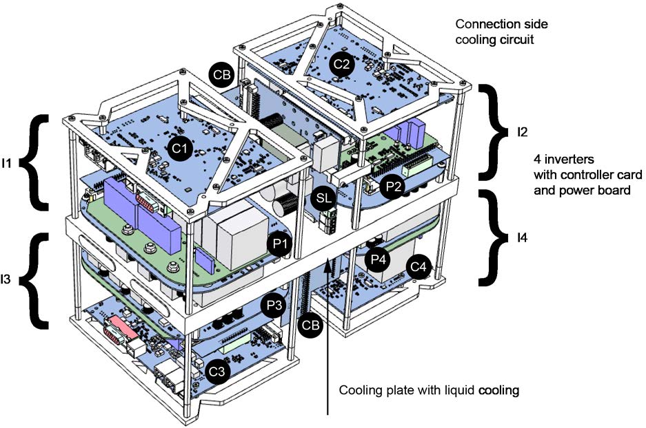
Our car drives the rear wheels with two electric motors, controlled by one inverter. The inverter has a liquid cold plate built into its base, and the motors wear 3D-printed nylon water jackets designed by an earlier team member in 2020. The battery cooling is not part of my work.
The problem I had to solve is simple to state: keep the motors and the inverter inside their temperature limits over the roughly 22 km endurance race, and end up with a parts list the team can order directly.
But at the start we had no cooling loop laid out, no parts chosen, and no data from the car. What I could find was mainly the makers’ data sheets and a 2020 motor jacket study from our own team. So this could not start from “which pump and which radiator to buy”. I first had to work out how much heat the system has to carry, how much water it needs, and how much pressure it will see.
Research Method
I started from other Formula Student teams’ public reports, to see how they went about this. My thinking was: borrow wherever it helps, but do not decide that a part suits our car just because another team used it.
My main reference is TU Brno’s Dragon e1, because its configuration is the closest to ours: two rear motors, one inverter. They set the requirement for each part first, measure each pressure drop, and then read the working flow where the pump curve crosses the loop curve. They also run the two motors in parallel and use 13 mm hose. That gave me a fairly complete approach.
The other reports each had their use. The Politecnico di Torino study fixes the heat first and then picks the radiator; the inverter loss model, the 1.2 heat factor, and the magnetic-drive pump I used later all have their precedent there. The University of Calgary (UCR) runs one pump with two motorcycle radiators, wrote a fan requirement, and checked flowmeters by timing a bucket fill. The University of Akron material has the only public wind-tunnel curve I could find for a catalogue motorcycle radiator. Chalmers used the same pump I studied, though they ran two in series.
For the motor jackets I still had to go back to our team’s own 2020 report. The makers’ data sheets and the Formula SAE 2026 rules settle the temperatures, flows, derating, water quality, and the catch-tank requirements.
With that material I could start calculating our heat, comparing loops, and choosing parts. CFD comes later, to check the calculations in front of it — not to run a simulation picture first and then explain backwards why the design works.
Heat Load and Limits
How big the cooling loop has to be depends on how much heat it has to carry, so that is the number I needed first.
Because the car has no logged drive data, I could only estimate the heat at steady speeds from road load. I took 40, 55 and 60 km/h, and the heat rises steeply with speed. That is because motor loss grows with torque and inverter loss with current.
So I used the highest, 60 km/h, as the design speed, which stays on the safe side. But it remains a calculation assumption, not a measurement from the car. Once real current is logged in a real endurance run, this number may have to change.
At 60 km/h I first work out the wheel force from road load, then read the motor loss from the maker’s loss maps. The inverter is the awkward one: I have no loss map for it, so I estimate with a published model for this type of module.
After that I multiplied the heat by 1.2, which means keeping 20% of margin. I do this for two main reasons:
- I want the radiators to last more than one season. If a later car is faster and more powerful, the heat will probably grow too, and I do not want an undersized cooling system to limit the car then. Having bought the radiators, I want to keep using them for several seasons. This also follows the Politecnico di Torino practice.
- The steady-speed calculation leaves out acceleration. A real endurance run never holds one speed, and without car data I cannot say how much extra heat acceleration brings. Teams I read either add a flat 300 W or multiply by 1.5. Comparing them, I chose 1.2. But I cannot claim this 20% covers all acceleration; it is the value I take at this stage.
Multiplying by 1.5 puts the loop heat at about 1240 W, above the 1150 W two radiators are expected to carry. The other way round, with no factor at all the design heat would be only about 850 W and the radiator margin would look like about 36% instead of today’s 14%. So this factor moves the final result a lot, and I cannot treat it as a verified number.
In the end I get about 436 W for the inverter cold plate and about 508 W for the two motors together. I also reserve 60 W for the water pump, taken from the maker’s electrical power ceiling for this pump family; the heat that actually reaches the water is not necessarily that high. Together, the loop is designed for about 1005 W.
This number changed several times while I was settling the calculation method. So that different spreadsheets cannot hold different versions, one design file now owns it.
With the heat fixed, the next question is how hot each part may get.
Take the inverter. The maker rates the cold plate at 25 °C inlet water and a surface below 40 °C. The problem is that I design for 32 °C air on a summer track day, and a radiator cannot cool water to 25 °C in that. Luckily the maker also publishes a derating table: full torque is allowed with the plate surface up to 50 °C, and torque falls to zero at 60 °C. I also saw two teams that keep the plate near 50 °C. So I set 50 °C as the plate design limit. This does depart from the maker’s rated condition, and I recorded it as a departure in the report.
The motor is similar. The maker’s rating assumes 40 °C water, but the water may run warmer at a cost of 1% per kelvin, up to 60 °C. So I set the motor inlet limit at 60 °C and accept losing part of the performance when the water runs that warm.
As for the minimum flow, the inverter cold plate requires 10 L/min and each motor 4 L/min.
Loop Topology
Knowing the heat and the limits, I still could not go straight to buying parts, because first I had to decide how the water flows.
For example, whether the two motor jackets run in series or in parallel, and where the radiators sit, both change the flow and the pressure drop. Using the one measured radiator curve I had found, I compared five connection schemes: several one-loop orders and one two-loop version.
The result surprised me a little: none of the five exceeded the temperature limits, and the one-loop versions differed by only about 1 K. In other words, on temperature alone there was almost nothing to choose.
What really separated them was the pump. One loop needs one pump carrying about 66–102 kPa; the two-loop version needs two pumps at about half the pressure each. I still chose the one-loop scheme, because one fewer pump means one fewer part to buy, to mount and to power, and one less 12 V supply line. The temperature difference was really small.
My scheme is as follows: water leaves the pump and passes through the left radiator, the inverter cold plate, and the right radiator in order, then splits into two branches through the two motor jackets, rejoins, and returns to the swirl pot. The two jackets are in parallel not to make the diagram tidy, but because it clearly cuts the pressure the pump has to overcome; I come back to this in the pump calculation.
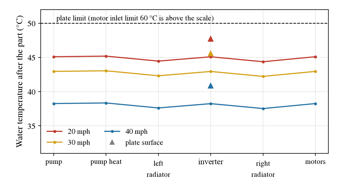
One more result surprised me: over the whole loop the water warms by only about 1.4 K. In other words, how hot the water runs depends mainly on how much the radiators cool it, not on which heat source sits in front.
Of course, whether the one-loop scheme really runs still waits on the pump test. If one pump turns out not to move the water, the two-loop version remains the fallback.
Radiators
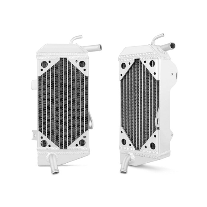
The car has one radiator position on each side, so space has basically decided the number: two at most, and the problem cannot be solved by adding more.
I looked for a motorcycle radiator that can actually be bought, because the team only buys catalogue parts. Picking a model hit a problem: many sellers give only length, width and port sizes, with no data to calculate heat rejection. I needed to know how much heat a radiator rejects at different air speeds, ideally from a wind-tunnel test. In the end I found exactly one public curve that qualified.
I use a simple relation to calculate: heat rejected is about the radiator’s K value times the water–air temperature gap. K, in W/K, means roughly how many extra watts the radiator carries for each extra kelvin of gap.
In that wind-tunnel test, at 20, 30 and 40 mph the K values are 38, 46 and 80 W/K. The report does not state the air temperature, so I checked at 15, 20 and 30 °C and kept the smaller K values, so as not to overestimate the cooling.
Then I thought: to hold the inverter plate surface below 50 °C, what is the smallest K the radiators must have? Air at 32 °C, plus a gap left between the plate surface and the water. That works out to about 33 W/K per radiator for two in series, or 62 W/K for a single one.
I selected at the lowest tested speed, 20 mph, rather than the fast case that cools best. At that speed each of the two radiators measures about 38 W/K against a needed 33 W/K, about 1.17 times. A single radiator would not qualify until 40 mph. So I decided on one radiator per side.
Under these conditions the plate surface comes to about 47.7 °C, and the water entering the motors stays below 44 °C. Before the plate touches the 50 °C limit, the two radiators are expected to carry about 1150 W, about 14% above my 1005 W design heat.
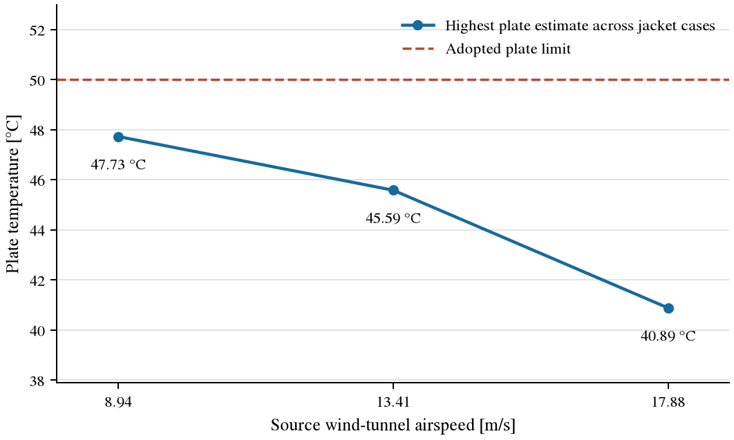
There is one more thing I am worried about. The plate sits only about 2 K below 50 °C, and my error in reading the curve is about the same size. More troubling, the test does not state the year of the radiator it measured, so I cannot yet be sure the model I would buy today matches the one tested.
So 1150 W and 14% are calculation results, not performance measured once the radiators sit in the sidepods. If the measured cooling falls short, we have no room for a third radiator. At that point the only option is limiting power output, and the maker’s own temperature derating cuts torque anyway.
Pump
The radiators settle whether the heat can be carried away; the pump has to settle whether the water can actually run through the loop at the flow we need.
You cannot just read a pump’s stated “maximum flow”, because with the cold plate, jackets, radiators, hoses and fittings attached, every one of them holds the water back. I add up these pressure losses into the loop’s own pressure curve, then find where it crosses the pump curve. That crossing point is the flow the pump can actually deliver.
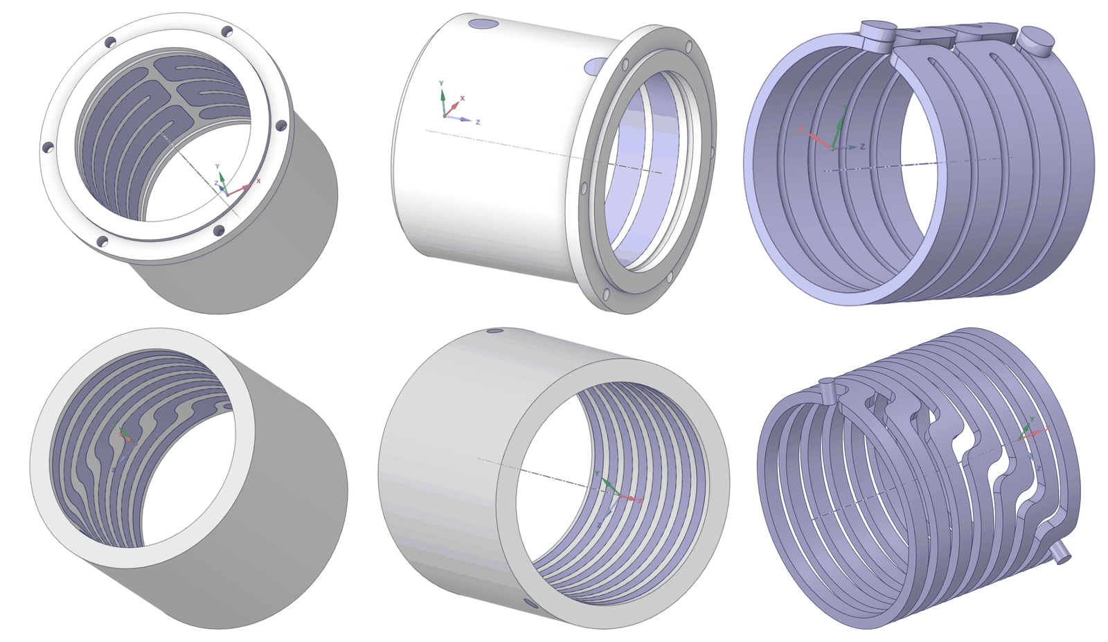
The hardest part here is the two motor jackets. The inverter maker publishes no pressure-drop curve for the cold plate, and nobody has measured our printed jackets. What the jackets have for reference is still the team’s 2020 simulation.
That report gives about 10.7 kPa per jacket at 5 L/min and about 38.8 kPa at 10 L/min. I use it as the design basis for a simple reason: it studied exactly the hardware on our car.
But I did not take the result on faith. The groove inside the jacket is about 7 × 5 mm, wound in seven rings, with 7 mm ports. Calculating from that geometry by hand, I get 41–102 kPa at 5 L/min, about 4 to 10 times the 2020 simulation. Later I also calculated it in OpenFOAM: about 130 kPa per jacket at 10 L/min. And when I test a straight pipe with the same method, this mesh type underestimates friction by 22–31%, so 130 kPa itself may still be low.
Three results this far apart, and I did not average them. An average would look nicer, but it would not tell which number is closer to the truth. At this stage I still design with the 2020 curve and leave the hand-calculation and CFD disagreement in the report. Only a bench test of the jackets will show the real value.
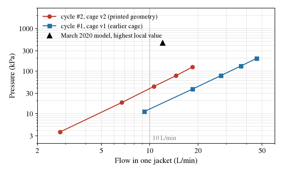
This is also why I insisted on the two motor jackets in parallel. On the curve currently adopted, two jackets in series both passing 10 L/min would need about 94 kPa; in parallel, each jacket sees about 5 L/min and only about 13 kPa. Since pressure drop grows roughly with the square of flow, half the flow makes a very visible difference.
I first compared a small automotive water pump, but near 10 L/min it offers only about 0.7 bar, below the loop pressure I had calculated, so I did not choose it.
The final choice is a magnetic-drive circulation pump. The maker gives this family a maximum head of 1.73 bar, against a current loop estimate of 0.66–1.02 bar. Also, a Chalmers Formula Student car has used this pump, so there is at least one real case to compare against.
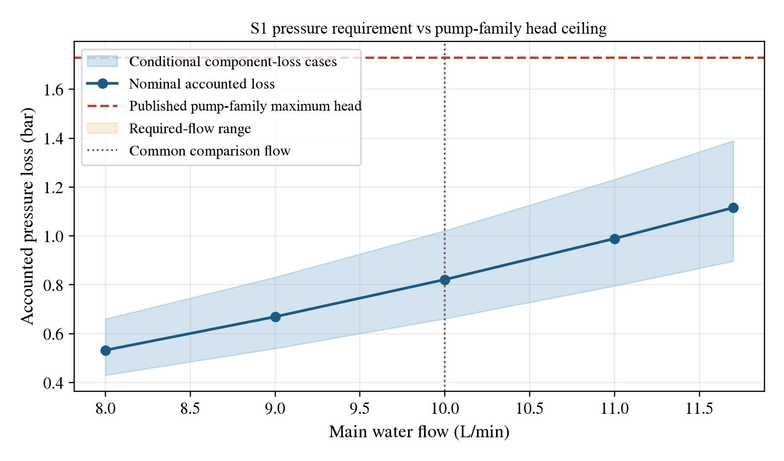
But one important problem is still unsolved: the maker publishes no full performance curve for this pump at 12 V, and 12 V is what our car uses. Maximum head and maximum flow cannot happen at the same time, so 1.73 bar alone does not prove it has enough pressure at 10 L/min.
If testing later shows one pump is not enough, I would first check whether the car can supply 24 V and run the pump at 24 V; then consider a second pump in series; and only last change to two loops. That order keeps the changes as small as possible.
But before discussing a second pump, the jackets have to be measured. If the jacket pressure drop really is as high as my hand calculation, the whole pump choice may have to be redone.
Hoses and Fittings
For hose I settled on 13 mm, weighing water speed, pressure drop, and whether the fittings can really be mounted on the car.
At 10 L/min the water in a 13 mm hose moves at about 1.26 m/s and loses about 1.8 kPa per metre. At 11 mm the pressure drop would be about 2.3 times higher. Our pump has little certain margin as it is, and I do not want the hose to eat a large piece of it.
A 16 mm hose would of course lower the loss further, but the 16 mm fittings I could find do not match the small threaded ports on the cold plate and sensors, and many positions would need adapters. That is not only fussy, it adds more joints. So on balance I chose 13 mm.
One dimension still cannot be ordered from a drawing alone: the 2020 CAD writes the jacket ports as 7 mm, but the physical part must be measured with a caliper. Until that dimension is confirmed, the hose-to-jacket fittings cannot be finalized.
Fans
When the car is quick, the oncoming air blows through the radiators by itself; at low speed it does not, so each radiator also gets a fan.
I took the requirement from a team that uses two similar radiators: 5 m³/min of flow at 140 Pa of static pressure. A 120 mm axial fan I found provides about 148 Pa at 5 m³/min on the maker’s curve.
That looks 8 Pa above the requirement, but reading that curve alone carries about 10 Pa of error. So all I can say today is that this fan roughly meets the requirement on paper, not that it really has 8 Pa to spare. It still has to be measured with the radiator and the sidepod around it.
Flowmeters and Temperature Sensors
I need flowmeters not to display a number on the car, but to confirm the inverter cold plate really has 10 L/min and each motor really has its own 4 L/min.
The flowmeters I chose are accurate to about 5%. Allowing for that error, the plate line should show at least 10.5 L/min and each motor at least 4.2 L/min. Otherwise the display can read exactly the maker’s minimum while the real flow is still a little short.
Nor can the flowmeters be fully trusted out of the box. I plan to check them the simplest way: fill a bucket, time how long a known volume takes, and work out the real flow. The Calgary team used the same method.
Temperature is harder to measure accurately. At my heat and flow, the water warms only about 0.6 K across the inverter plate. To keep the measured heat within 10%, the difference error caused by the two sensors themselves must stay under about 0.06 K, ten percent of 0.6 K.
Ordinary sensors are rarely that consistent by nature. So I plan to calibrate all six temperature sensors together in one bucket of constantly stirred water, so that they read as alike as possible at the same temperature. Why six? Because the inverter plate and the two motor jackets each need one sensor at the inlet and one at the outlet.
Swirl Pot and Catch Tank
A cooling loop should not keep air in it. If air reaches the pump or the cold plate, some spots can run dry, and the cooling breaks down.
So I will put the swirl pot at the highest point of the whole loop, so that air collects there, which also makes the first fill and later bleeding easy.
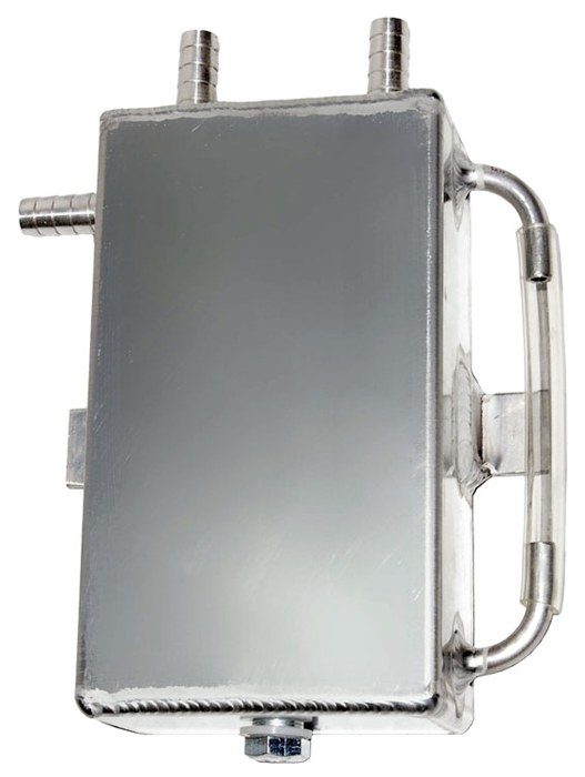
Separately, the Formula SAE rules require a catch tank on the vent line, so the vent line gets one too. The two tanks do different jobs: the first vents the cooling loop, the second catches any liquid the vent line may let out, to satisfy the race rules.
Coolant
Coolant looks like the simplest item, but here too we have an unresolved risk.
The race rules allow plain water with no additives. I first wanted distilled water, but sourcing it was awkward, and the team decided to switch to filtered tap water. That costs nothing extra, and the rules allow it.
The catch is that allowed by the rules is not the same as best for the parts. Minerals in tap water can slowly scale the narrow 7 mm passages of the water jackets, and its chloride can speed up corrosion where aluminium meets brass. More troubling, the inverter maker also asks for corrosion inhibitor in the coolant, and our current plan does not meet that.
I did not write this into the report as “no problem”. Instead I recorded it explicitly as a departure from the maker’s requirement.
If we do end up running filtered tap water, I at least require a pH and conductivity check before the first fill, and fresh water every season. If the water is out of range, or scale shows up when the loop is opened, we switch to deionised or reverse-osmosis water. As for long-term corrosion, these measures only lower the risk; they cannot replace a real material-compatibility verification.
The Role of CFD
This time I did not make CFD the first step of the design. I fixed the main parameters with calculations I could check, then used CFD to look for anything clearly wrong.
I did not throw the whole cold plate or water jacket into OpenFOAM straight away. The first run was an ordinary straight pipe, because a pipe’s pressure drop can be checked against ready-made formulas. In the laminar case the difference between CFD and the textbook value is within 0.5%; in the turbulent case the result runs 4.5–5.1% below the smooth-pipe formula. That one step at least told me the basic setup is not absurd.
Only then did I calculate the real inverter cold plate and one motor jacket. But the mesh refinement of these two models is not enough, and the results cannot directly pick parts.
CFD currently puts the cold plate pressure drop at about 13–18 kPa at 10 L/min. At the design heat the plate surface comes out about 1.6 K above the inlet water; my hand calculation gives about 3 K.
The two methods do not fully agree, and I kept the hand value for the design. Not because the hand calculation is necessarily more accurate, but because the CFD has not yet had enough mesh verification, while every assumption and every number in the hand calculation is something I can check myself. If the CFD mesh and measured data are completed later, I can then decide whether to change the number.
Purchase Plan
Only at this point did I start putting parts on the purchase list one by one.
The team only buys catalogue parts that can be ordered directly, so I found one clear model and a public product page for every item, so that we do not discover at ordering time that all we have is a vague product name. The full list: pump, two radiators, two fans, a 12 V converter, the swirl pot, the catch tank, valves, hoses, fittings, splitters, flowmeters, temperature sensors and clamps.
But I do not want to buy everything at once, because the biggest risk right now is still the water side. If the pump cannot drive the jackets at all, buying the most expensive radiators first does not solve anything.
So I split the purchase into two batches.
Batch one buys the water-side items: the pump, the parts for filling and venting, the flowmeters, the temperature sensors and the hoses. Together with the cold plate and printed jackets the team already has, we can circulate water on a bench first.
The test order also follows what I worry about most: first measure the pressure drop of the cold plate and one jacket separately, then the pump’s performance curve at the car’s real voltage, then connect the complete loop. Only when the cold plate reaches 10 L/min and each motor 4 L/min, with no leaks in the loop, do I consider this gate passed.
Batch two buys the radiators and fans. They cost more, and without the real sidepods there is no way to test the ventilation conditions on the car. So I want to wait until batch one passes before spending that money.
One more small but mandatory step before ordering batch one: measure all four jacket ports. Otherwise, if the port size is wrong, the fittings come back and cannot be mounted.
What Is Still Unsolved
Writing this far, I cannot say the cooling system is verified. It is a design with calculation behind it that also lands on orderable part numbers, but not one part has finished testing on the car.
What worries me most:
- The pump may not be enough. The maker has no full 12 V curve, and a maximum head alone cannot prove it can deliver 10 L/min.
- The jackets’ real pressure drop may be far above plan. I am using the 2020 simulation, but my own hand calculation and CFD both came out higher.
- The radiator margin is thin. At 20 mph the K value is only about 17% above the requirement, and the total capacity is about 14% above the 1005 W design heat. The year of the tested radiator is unclear, and once mounted in the sidepods it may behave differently from the wind tunnel.
- 1005 W is not a measured heat. It comes from a steady-speed estimate times my chosen factor of 1.2. The heat in a real endurance run is still unknown.
- The water we chose does not meet the inverter maker’s coolant requirement. Water quality and long-term corrosion both need continued checks.
So the next thing I want to do is not to keep making the simulations prettier, but to move the jackets, the cold plate and the pump onto a bench and measure the real flows and pressure drops. With those numbers I will know which of the judgements above were right, and where the design still needs to change.